
Mixbus provides a wide range of meters. Each meter is suited to its particular task.
Some DAWs try to put a lot of different scales on a single meter, and/or they expect the user to switch modes to see different values. Mixbus provides several “different” meters in the places where they are useful.
Track Meters
![]()
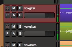
In the editor, to the right of each track’s name, you’ll find a small meter that indicates the channel’s level. This meter grows in height when you increase the size of the track. This meter follows the settings in “Preferences->Meterbridge->Default track meter type”. The colors for peak-hold time, among other options, can be applied to these meters. The meter follows the selection for “meter point” in the bottom-right corner of the associated mixer strip. When a channel is record-armed, the meter point will automatically move to meter the channel’s input. Due to their scaling, and their location in the editor window, these meters are well-suited to checking your recording levels while recording
Master Meter (editor toolbar)
![]()

In the top of the transport toolbar, you will find a meter indicating the master bus. This meter can be hidden in Preferences->Appearance->Toolbar. This meter follows the settings in “Preferences->Meterbridge->Default meter type for master bus”. By default, Mixbus uses a K-14 meter (the same scaling that is used for the master bus K-14 meter). In addition, there is a peak-hold indicator with adjustable decay time. The colors for peak-hold time, among other options, can be applied to this meter. This meter serves to provide a condensed view of the master bus output when you are editing
Meter Bridge Window
![]()
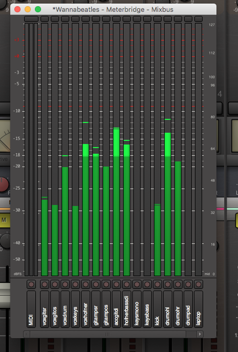
The Meter Bridge window can be accessed from the main menu, under “Window”. The meters in this window follow the settings in “Preferences->Meterbridge”. The colors for peak-hold time, among other options, can be applied to these meter. The meter-bridge is well-suited to tracking a live band, as you can see several high-resolution meters in a condensed view. You can also show the track rec-arms and monitor switching from this window
Channelstrip meters
![]()

To the right of each channel’s fader, you’ll find a small meter that indicates the channel’s level. The meter follows the selection for “meter point” in the bottom-right corner of the associated mixer strip. When a channel is record-armed, the meter point will automatically move to meter the channel’s input. The scaling and ballistics of these meters are fixed, so that they are directly comparable across all channels of the mixer. The channelstrip meters are well-suited to balancing your mix. The scaling is optimized to show the upper range ( -20dB to 0dBFS ), and it is scaled to match the fader and the compressor threshold sliders.
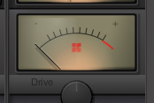
Channelstrip Compressor Gain-Reduction meter
![]()

This meter indicates the gain-reduction applied by the channelstrip compressor ( see Compression Techniques ). Each light indicates 1dB of gain reduction.
Mixbus & Master Bus – Tape Saturation Meter
![]()
A Tape Saturation meter is provided on each mixbus, as well as the master bus. This meter indicates the amount of distortion applied by the tape-saturation stage. If the meter is fully left, then no distortion is applied. If the meter is fully right, then the signal is heavily distorted. You can use the “Drive” knob to adjust the amount of tape saturation / distortion.
Master Bus K-14 Meter
![]()

The K-14 meter is an RMS (averaging) meter, originally specified by mastering engineer Bob Katz as a means to compare and help control the dynamic range of pop music mixes. (see : http://www.digido.com/how-to-make-better-recordings-part-2.html ) Use this meter to monitor the perceived “loudness” of your music mix, and compare the loudness of your mix to other mixes of the same genre
The K-Meter displays the level of the signal directly before the output of the master bus. The K-Meter comes after the fader, EQ, plugins, and final limiter in the master bus.
If the K-14 meter indicator is straight up, at 0, this indicates that the sound’s average level is at -14dBFS. This was selected as a good target for most pop/blues/jazz/rock recordings. At this level, a song will sound quieter than most contemporary pop music, but when the listener turns the volume up to match, the increased dynamic range of this mix will allow the song to sound much better than a typical pop song played at the same volume.
Increasing the volume beyond the “0” indicator will result in a louder mix, at a cost of decreased fidelity and impact when the user turns the volume up.
Master Bus Phase Correlation Meter
![]()

The stereo correlation meter provides an indication of the “mono compatibility”, or stereo width, of your mix. The indicator uses a bright bar which simultaneously indicates the range of in-phase (highly correlated) and out-of-phase (decorrelated) sounds in your mix.
- If the indicator is fully to the right, and yellow, this indicates a completely “mono” mix. (the signals in the left and right channels are the same)
- many signals (such as a spoken-word recording with one microphone) should be mono.
- If the indicator is fully to the left, and fully red, this indicates a mix that is completely “out of phase”, in other words the left and right channels are equal, but one is inverted with respect to the other. This almost certainly indicates a technical fault which should be investigated.
- If the indicator is largely to the right, and green, then it indicates a mix with some stereo width, but largely mono compatible. This is optimal for pop music recordings that might be played in a variety of playback systems.
- If the indicator is in the center, showing a range of red and green, then the mix is very wide stereo. This is probably not optimal for pop/rock recordings, but can be acceptable for natural or orchestral recordings. Mono compatibility of this mix is questionable.
Mono compatibility is largely defined by low frequencies. If your mix indicates poor mono compatibility ( red bar on the left ), then you can probably solve this by reducing the number of bass instruments in the mix, high-pass filtering any non-bass instruments, and high-pass filter any stereo effects, such as reverb, in the mix.
Master Bus Limiter
![]()

Each segmented LED represents 1 dB of gain reduction in the Master Bus Limiter. The master bus limiter is a brickwall, lookahead limiter that prevents the digital signal from exceeding -1dBFS. *When mixing, use this bright yellow meter to alert you when you “would have” exceeded the -1dBFS threshold. *
Post your comment on this topic.