
The input channel strip is the fundamental element in the mixing window. This is where an audio signal is routed, processed, and then sent to either a mix bus or the master channel. An input channel strip can be mono or stereo.
- New in Mixbus32C v9 are the channel Gate/Expander processor, and expanded controls on the Leveler/Compressor/Limiter. Separate buttons to view the Gate, Compressor, Input Switcher, EQ and Bus Sends facilitate operation with video monitors of height less than 1200 pixels. Display of all at once is only possible if you have a 4K HD monitor. The following picture shows none of these sections displayed.
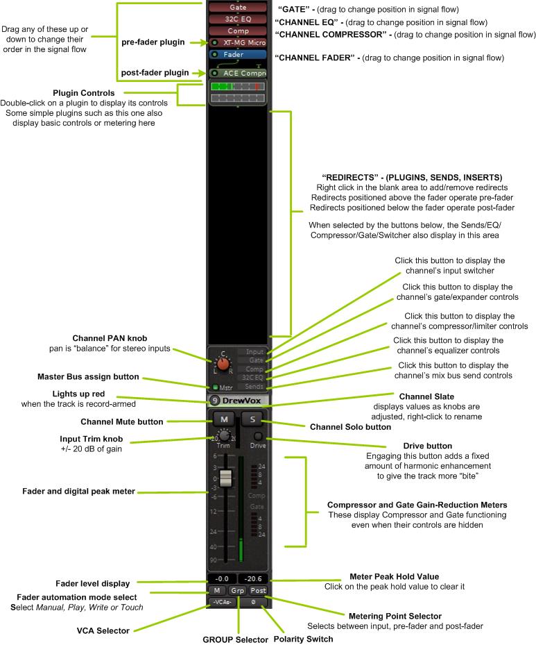
The features of the input strip visible in the above figure include:
- Redirect Section – see section Redirects – Plugins, Sends & Inserts. This area is where plugins can be inserted. At the top the positions in the signal flow of the Gate, EQ, Compressor and Fader are displayed by default.
- Stereo Pan Knob
- Master Bus Assign (“Mstr”) : when this is lit, the signal will be sent directly to the Master bus (in addition to any mixbus assignments)
- Channel Mute and Solo
- Input Trim knob : the input trim value is applied immediately after track playback, and BEFORE any plugins in the redirect box
- 5 buttons select the visibility of the Input Switcher, Gate, EQ, Compressor, and Bus Sends controls
- Drive button adding harmonic enhancement to the track
- Fader
- Meter : the channel meter is a digital peak-reading meter; the scale is the same as the fader
- Compressor and Gate gain reduction meters – these are always active and visible even if the Gate and Compressor Controls are hidden
- Fader level : this displays the curent fader position, in dB. Click to enter a value.
- Meter peak-hold : this displays the loudest digital-peak value that has been detected by the meter. It turns red when the value is over 0dBFS. Click to reset the value.
- Fader Automation selector : select between Manual, Play, Write, and Touch. This control only affects the channel’s fader
- Group selector : click this button to assign the channel to a Group ( see: Groups )
- Meter Position selector : click this button to select the meter position ( Input, Pre-Fader, Custom, Post-Fader, Output )
- Polarity switch
- VCA Assign
The features of the input strip NOT visible in the above figure include:
- The Rec/Input switcher – see section Rec/Input (“Switcher”) Section
- The channel gate section – see section Channel Gate Expander Section
- The EQ section: see section EQs
- The Compressor/Limiter/Leveler Section – see section Channel Compressor Limiter Section
- the Bus Sends section – see section Sends Section
These sections are displayed by selecting the buttons to the right of the Pan knob. These are not unique to the particular channel strip, for example selecting the EQ will display the EQ section on ALL the channel strips, selecting the compressor section on any channel strip will display this section on ALL channel strips AND the 12 mix buses.
How many of these sections can be displayed at once depends on the resolution of your video monitor. A 4K HD monitor is required if you want all sections to be displayed at once.
Additionally, there is a preference setting under Edit->Preferences->Size and Scale that allows you to choose how many of these sections can be displayed at once, allowing you to optimize the display to your monitor.
- The following picture shows the Input Switcher section displayed.
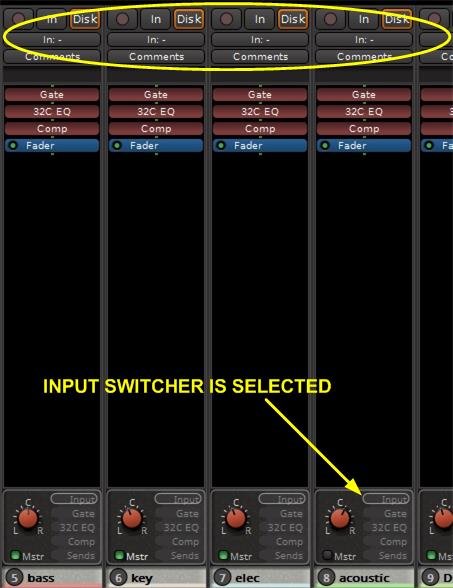
Note that selecting the input switcher displays it on ALL channel strips.
- The following picture shows the Gate section displayed.
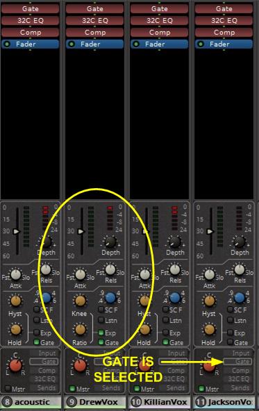
Note again that selecting the Gate section does so on ALL channel strips.
- Some features of the Gate Section:
- both Gate and Downward Expander functions available
- Hysteresis and Hold controls in Gate mode. In Expander mode these knobs become Knee and Ratio controls
- Sidechain filter: this is a bandpass peaking filter in the gate sidechain path The “LSTN” button allows listen to the sidechain path without affecting the main signal path
- Threshold and Depth controls
- “Attack” and “Release” knobs: allows adjustment of the gate attack and release time constants
- The following picture shows the compressor section displayed.
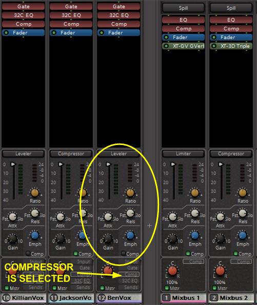
- Some features of the Compressor Section:
- Makeup Gain – provides up to 10dB of Makeup Gain; this gain is only active when the compressor is enabled
- Emphasis filter: this is a sliding High-shelf filter in the compressor sidechain path
- Threshold – the threshold indicates when the compressor will begin working on the signal; reduce the threshold slider to compress more
- NEW! “Attack” and “Release” knobs: allows adjustment of the compressor attack and release time constants
- The following picture shows the EQ section displayed.
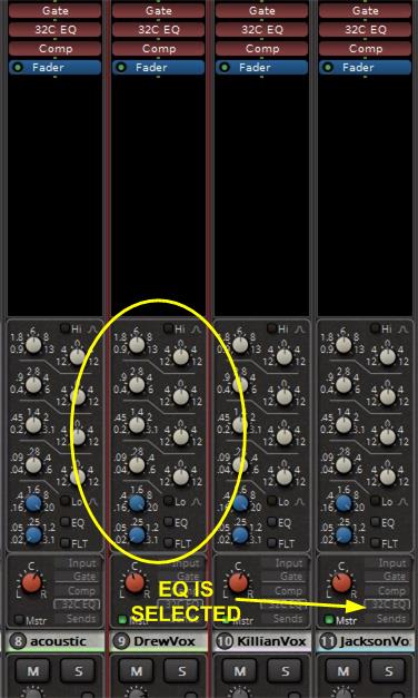
Some features of the EQ are:
- 4 EQ bands, each with +/-15 dB gain:
- “Mid” bands are proportional-Q peaking bands ( Q increases with additional boost/cut )
- Hi and Lo bands are shelving by default, Individual “Peak” buttons change the bands to proportional-Q peaking mode.
- “Mid” bands are proportional-Q peaking bands ( Q increases with additional boost/cut )
- The following picture shows the Bus Send section displayed. See the section Bussing
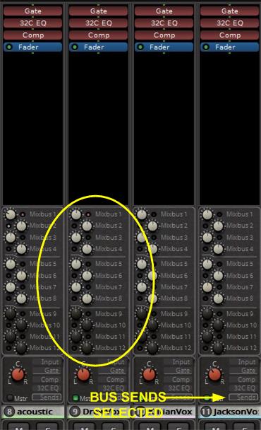
- Mixbus Sends Section:
- 12 mixbus sends, each with On/Off switch, and level control
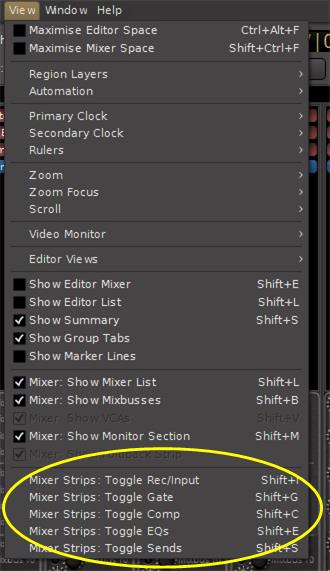
View Pulldown
There is an additional method for displaying the Gate, Compressor, EQ, Sends or Rec/Input menu on the channel strips. Rather than clicking the buttons on the channel strips, the View pulldown menu provides either a menu click or keyboard shortcuts for switching the display. As with clicking the EQ, Sends or Input buttons on the channel strip itself, the display changes for ALL channels, not just a selected channel. The figure below shows how to access these controls and also shows the associated keyboard shortcuts.
Other Buttons and Controls
Polarity
- Click this button to invert the signal’s polarity. On a stereo channel, you will see 2 polarity switches, one for each channel.
VCA
- Click this button to assign one or more VCA faders to control this channel’s fader and mute. See the section VCA Strip for details.
Grp
- Grouping links faders together for common control. Click this button to assign this channel’s fader to a group. See the section Groups for details.
M
- Click this button to select the desired fader automation mode. The choices are Manual, Play, Write, Touch and Latch. See the section Fader, Pan and Plug-in Automation for details.
General Operation
Channel strip operation is the same everywhere in Mixbus.
- mouse-click on a button to activate it
- to turn a knob or move a fader, click and hold on it and move the mouse up and down
- double clicking on a knob will snap it to its centere position
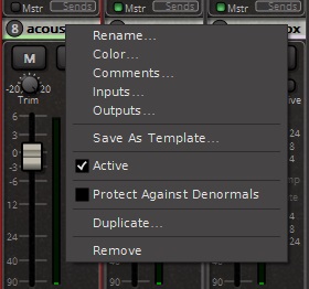
- right-clicking on the channel slate will bring up a menu where you can change the name, color, input or output routing, and other options:
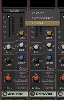
- When the Compressor is displayed, right clicking on the top button allows you to select between leveller, compressor or limiter operation:
Post your comment on this topic.
Patrick wrote: Mar 22, 2023
The whole page describing the Mixer channel strip needs to be revised. It currently provides details for version 8.
Thanks!