What is signal flow?
“Signal Flow” is the path that audio follows through an electronic system of wires, and/or its equivalent inside your computer. The “signal flow” of a recording starts with the performer, and ends with the listener. This incorporates the microphones, converters, computers, mixers, effects, amplifiers and speakers that make up the signal path. In this manual we refer to ‘signal flow’ of Mixbus itself. The signal flow starts with the A/D converter of your soundcard’s input, and proceeds to the D/A converter on the output. Mixbus’s signal flow consists of input tracks, mixer-strip processors, buses, and monitor stages that execute the various processes of recording, mixing, and exporting.
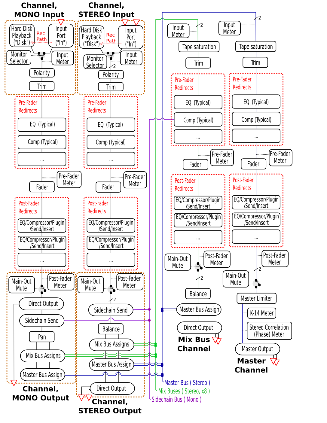
Mixbus’s signal flow
The Mixbus signal flow is modeled on an analog console.
Mixbus may have an unlimited number of mono and stereo channelstrips (Tracks). Each channelstrip may be assigned to any of the mixbuses, and/or directly to the master bus.
* In one small way, Mixbus differs from traditional mixing console: each of the mixbus assigns have level controls, so each of the mixbuses can be used as either an “aux send/return path” (using the level controls to adjust the send level) or a “grouping bus”, (using the hard assign buttons with the level control at unity) depending on the user’s needs. Typically in an analog console, a separate selection of aux sends and grouping buses are provided. If you are a live-sound engineer familiar with stage monitor consoles, then you already know about having a level control on each bus send, and Mixbus is exactly the same.
The “redirect” areas are represented by the black box at the top of the mixer strip. Sends, Inserts and Plugins are “redirects”, and they may be placed in any order, before or after the fader. If a redirect is above the fader, then it is considered a pre-fader redirect.
*An important tip about signal flow: The Mixbus “bussing” structure (mix buses + master bus) is stereo-only. Typically a channel has one (mono) or 2 (stereo) inputs. This defines the channel width through the channelstrip. However, it is possible to change the channel width via plugins. For example you can have a mono-input, stereo-output effect (such as a chorus or autopanner effect). The last redirect (plugin) in the post-fader redirect box will define the signal width just before it goes into the panning/bussing section. If the last plugin has a single (mono) output channel, then the mono panner will be used. If the last plugin has 2 (stereo) output channels, then the stereo “balance” panner will be used. If the last plugin has 3 or more channels, then the stereo “balance” panner will be used and the remaining channels will be ignored by Mixbus.
The signal flow through each plugin may be modified with Pin Connections.
*Not shown in the diagram is the Pre-Fader and Post-Fader send mutes. Sometimes when you mute a track, you still want a Send to remain active (for a headphone feed, for example). It is possible to disable the mute for pre- and post- fade sends separately. To enable or disable the pre- and post-fader send mute, right-click on the Mute button in the editor window.

Post your comment on this topic.