
The input channel strip is the fundamental element in the mixing window. This is where an audio signal is routed, processed, and then sent to either a mix bus or the master channel. An input channel strip can be mono or stereo.
- New in Mixbus 32C v6 are multiple display modes to facilitate operation with video monitors of height less than 1200 pixels. With the control buttons one can selectively display the Input/Rec section, the EQ section, or the mixbus Send section. The following picture shows none exposed.
- Also new are the positions of the Polarity and VCA assign buttons. They are now always displayed at the bottom of the channel strip.
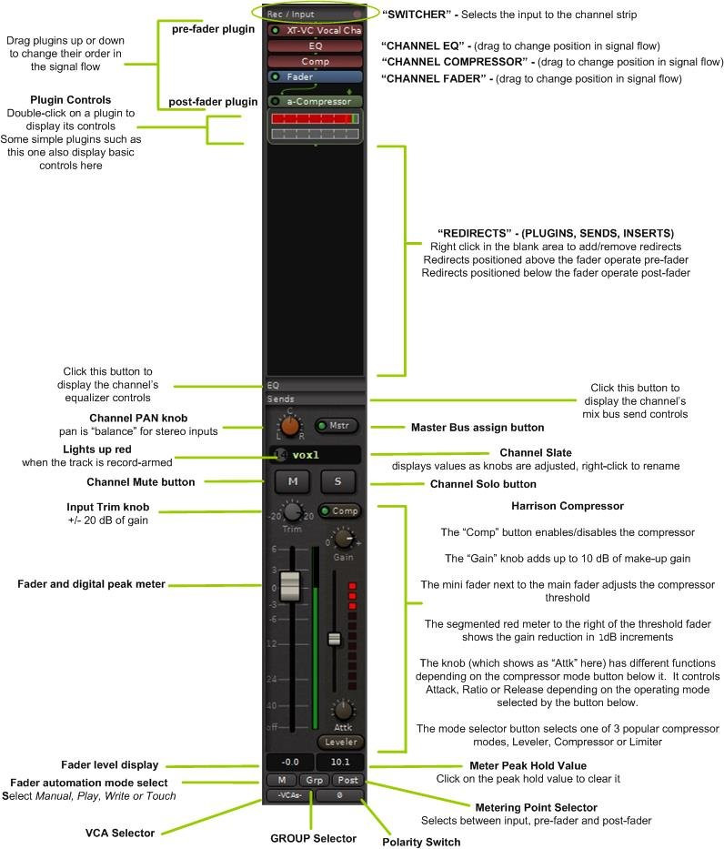
The features of the input strip include:
- The Rec/Input switcher – see section Rec/Input (“Switcher”) Section
- The redirect box – see section Redirects – Plugins, Sends & Inserts
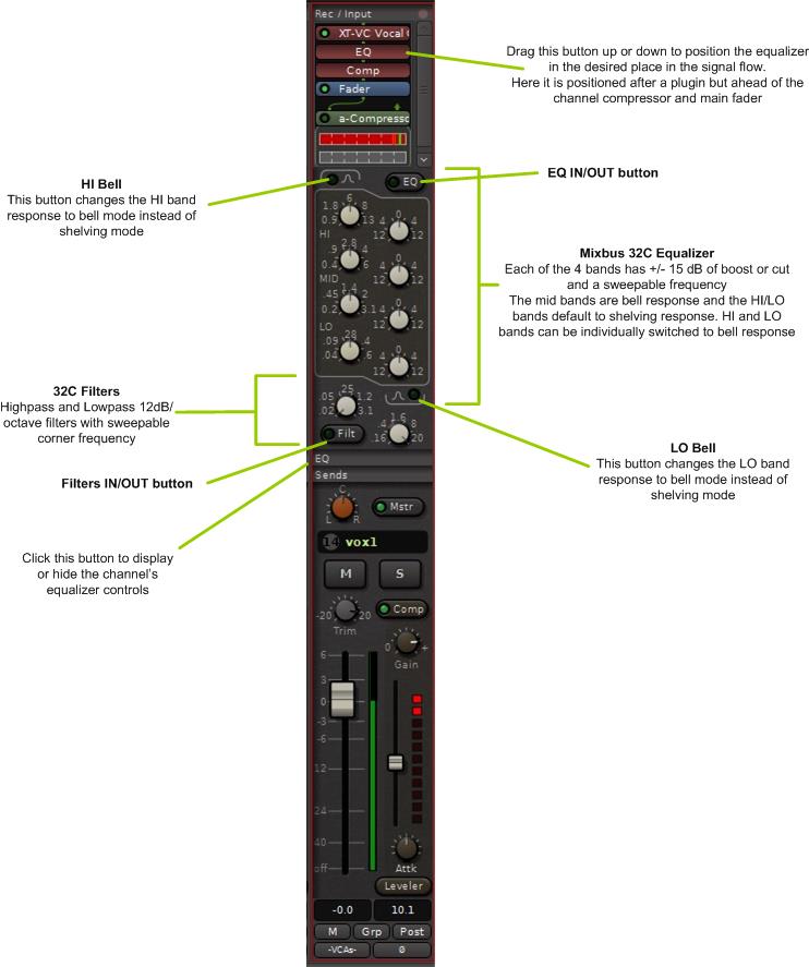
- The EQ section: see section EQs
- EQ “IN” – Enables the EQ section
- 4 EQ bands, each with +/-15 dB gain:
- “Mid” bands are proportional-Q peaking bands ( Q increases with additional boost/cut )
- Hi & Low bands are shelving by default
- Individual “Peak” buttons for Low and High bands: change the bands to proportional-Q peaking mode.
- Filter “IN” – Enables the Filter section
- Filters are second-order ( 12 dB/octave )
- High Pass Filter Frequency knob
- Low Pass Filter Frequency knob
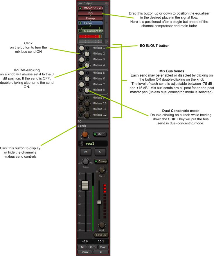
- Mixbus Sends Section: see section Bussing
- 12 mixbus sends, each with On/Off switch, and level control
- Stereo Pan Knob
- Master Bus Assign (“Mstr”) : when this is lit, the signal will be sent directly to the Master bus (in addition to any mixbus assignments)
- Channel Mute and Solo
- Input Trim knob : the input trim value is applied immediately after track playback, and BEFORE any plugins in the redirect box
- Fader
- Meter : the channel meter is a digital peak-reading meter; the scale is the same as the fader and the compressor threshold
- The Compressor Section: see section Compression Techniques
- Comp “IN” – Enables the compressor section
- Makeup Gain – provides up to 10dB of Makeup Gain; this gain is only active when the compressor is enabled
- Threshold – the threshold indicates when the compressor will begin working on the signal; reduce the threshold slider to compress more
- Gain-Reduction meter – indicates gain reduction, in 1dB increments
- “Speed” & “Mode” knobs : see Compression
- Fader level : this displays the curent fader position, in dB. Click to enter a value.
- Meter peak-hold : this displays the loudest digital-peak value that has been detected by the meter. It turns red when the value is over 0dBFS. Click to reset the value.
- Fader Automation selector : select between Manual, Play, Write, and Touch. This control only affects the channel’s fader
. - Group selector : click this button to assign the channel to a Group ( see: Groups )
- Meter Position selector : click this button to select the meter position ( Input, Pre-Fader, Custom, Post-Fader, Output )
- Polarity switch
- VCA Assign
- The following picture shows the EQ section displayed.
- The following picture shows the mixbus Send section displayed.
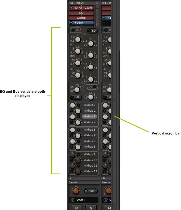
For monitors with at least 1200 pixel vertical height it is possible to choose to see both the EQ and the bus sends at the same time. To select this option go to Window -> Preferences -> Show All ->Appearance and select the box “Allow both the EQ and SEND sections to be visible on a strip”. The “EQ” and “Sends” buttons can still be used to display/hide each set of controls and view the plugin area.
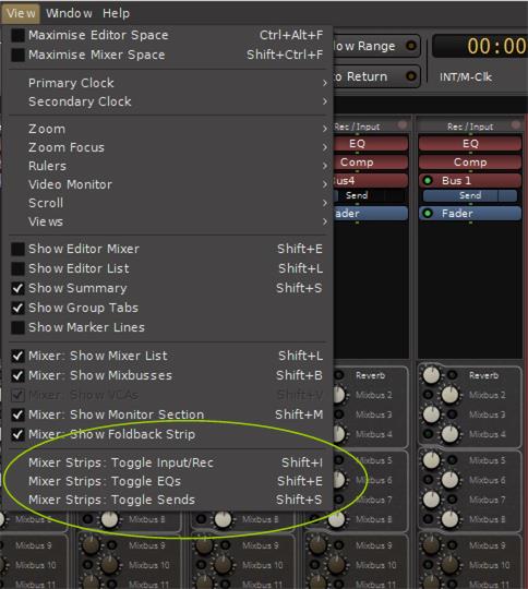
View Pulldown
There is an additional method for displaying the EQ, Sends or Rec/Input menu on the channel strips. Rather than clicking the buttons on the channel strips, the View pulldown menu provides either a menu click or keyboard shortcuts for switching the display. As with clicking the EQ, Sends or Input buttons on the channel strip itself, the display changes for ALL channels, not just a selected channel. The figure below shows how to access these controls and also shows the associated keyboard shortcuts.
Other Buttons and Controls
Polarity
- Click this button to invert the signal’s polarity. On a stereo channel, you will see 2 polarity switches, one for each channel.
VCA
- Click this button to assign one or more VCA faders to control this channel’s fader and mute. See the section VCA Strip for details.
Grp
- Grouping links faders together for common control. Click this button to assign this channel’s fader to a group. See the section Groups for details.
M
- Click this button to select the desired fader automation mode. The choices are Manual, Play, Write, Touch and Latch. See the section Fader, Pan and Plug-in Automation for details.
General Operation
Channel strip operation is the same as everywhere in Mixbus.
- mouse-click on a button to activate it
- to turn a knob or move a fader, click and hold on it and move the mouse up and down
- double clicking on a knob will snap it to its center position
- right-clicking on the channel slate will bring up a menu where you can change the name, colour, input or output routing, and other options:
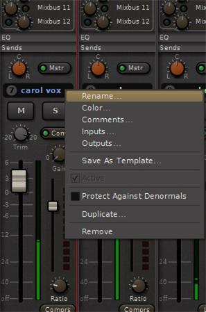
- right clicking on the compressor button allows you to select between leveller, compressor or limiter operation:

Post your comment on this topic.